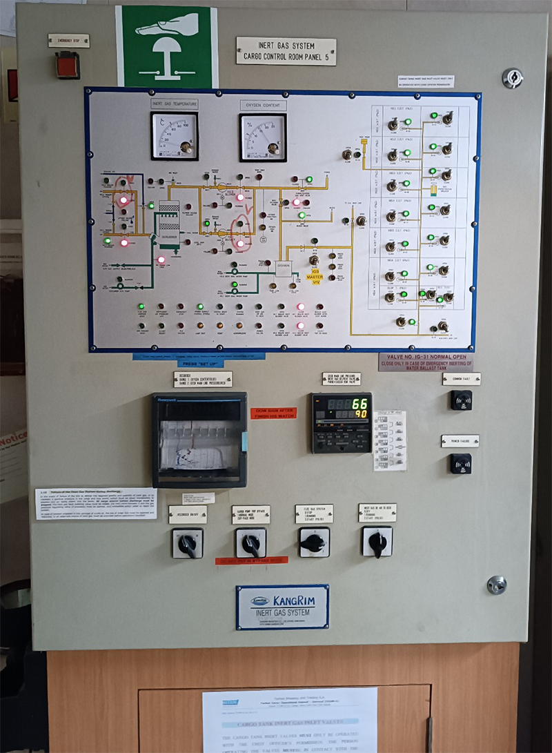
Inert Gas Generator System
Introduction
Oil tankers carry various grades of oil that can produce flammable vapors and gases during transit. Even with empty holds, dangerous gases may remain. When these vapors mix with oxygen at certain concentrations, explosions can occur—potentially causing property damage, pollution, and loss of life. To mitigate this risk, an Inert Gas System (IGS) is used onboard. This system may be a standalone setup or rely on flue gas from the ship’s boiler.
What is Inert Gas and the Inert Gas System?
Inert gas is a gas mixture with a low oxygen content (typically below 8%), which prevents the combustion of flammable hydrocarbon gases. By dispersing inert gas throughout the cargo tank, the system raises the lower explosion limit (LEL) and lowers the higher explosion limit (HEL), effectively reducing the risk of ignition. When the inert gas concentration nears 10%, hydrocarbon vapors become unable to ignite. For safety, this concentration is maintained around 5%.
In most IGS setups, flue gas from the ship's boiler is cleaned, cooled, and then directed into cargo tanks through pressure-vacuum (PV) valves and breakers. This maintains both tank integrity and a safe atmosphere. The system generally has two main components:
- A production facility to generate inert gas and deliver it (via blowers) to the cargo tanks under pressure.
- A distribution network to control the flow of inert gas into the designated tanks at the appropriate time.
Short Operation Principle
Boiler uptake gases are routed through flue gas isolating valves into a scrubber unit, where they are cooled, cleaned, and dried. Motor-driven inert gas blowers then transfer this treated gas to the tanks. Blowers are typically mounted on rubber absorbers and connected to the piping via rubber expansion bellows to minimize vibration.
The quantity of gas sent to the deck is controlled by gas control valves, while a pressure controller maintains deck pressure. If deck pressure falls below setpoint, valves open further; if it exceeds setpoint, valves restrict flow. These valves work together to keep both deck and blower pressures at safe levels. Before reaching the deck line, the gas passes through a deck water seal (acting as a non-return valve) to prevent any backflow of explosive gases from the cargo tanks.
After the deck seal, an inert gas relief valve equalizes any pressure buildup when the system is off. If both the deck seal and non-return valve fail, this relief valve vents gases from the tank to the atmosphere. An oxygen analyzer, positioned downstream of the blower, monitors gas oxygen levels. If oxygen exceeds 8%, it triggers an alarm and shuts down the system.
Components and Description of the IG System
- Source of exhaust gases: The IGS uses flue gases from boiler or main engine exhaust uptakes.
- Inert gas isolating valve: Connects or isolates the uptake from the rest of the system when not in use.
- Scrubbing tower: Flue gas enters from the bottom and passes through water sprays and baffle plates to cool, clean, and humidify the gases. This reduces SO2 by up to 90% and removes soot.
- Demister: Made of polypropylene or stainless steel, it removes moisture from the scrubbed gas.
- Gas blower: Typically includes both a steam-driven blower (for IGS operation) and an electric blower (for topping up).
- I.G. pressure regulating valve: Mounted downstream of the blower discharge to divert excess gas back to the scrubber, preventing blower overheating and stabilizing tank pressure.
- Deck seal: Usually a wet-type seal, preventing backflow of gases. A demister is included to remove moisture.
- Mechanical non-return valve: Another safeguard against backflow, located alongside the deck seal.
- Deck isolating valve: Completely separates the engine room system from the deck system.
- Pressure Vacuum (PV) breaker: Prevents over-/under-pressurization in cargo tanks. Includes a flame trap for safety during loading or discharge.
- Cargo tank isolating valves: Each cargo hold has a dedicated valve for controlling inert gas flow, operated only by authorized personnel.
- Mast riser: Remains open during cargo loading to maintain positive inert gas pressure and avoid excess pressure buildup.
- Safety and alarm system: A range of safety features protect the tank and associated machinery from operational hazards.
Alarms and Shutdown Procedures
- High scrubber level: Triggers an alarm and shuts down the blower and scrubber tower.
- Low seawater supply pressure (~0.7 bar) to the scrubber: Activates alarm and stops the blower.
- Low seawater supply pressure (~1.5 bar) to the deck seal: Triggers alarm and blower shutdown.
- High inert gas temperature (~70°C): Leads to alarm and blower shutdown.
- Low pressure post-blower (~250 mm wg): Causes alarm and blower shutdown.
- High oxygen content (8%): Triggers alarm and halts gas supply to the deck.
- Low level in the deck seal: Activates alarm and stops gas supply to the deck.
- Power failure: Results in alarm and shutdown of both blower and scrubber tower.
- Emergency stop: Triggers alarm and shutdown of blower and scrubber tower.
Various Alarms
- Scrubber low level
- Deck seal high level
- Low O2 content (1%)
- High O2 content (5%)
- Low lube oil pressure alarm
Working of the Inert Gas System
The core principle of inert gas production involves using flue gas from the ship’s boiler. High-temperature gases from the boiler uptake are cleaned and cooled in the inert gas system, then directed into each cargo tank through PV valves and breakers to ensure tank safety.
The system is broadly divided into two groups:
- Production system: Generates inert gas and delivers it under pressure (via blowers) to the cargo tanks.
- Distribution system: Regulates and directs the inert gas flow into the designated tanks at the required times.